
Table of Contents
ToggleIntroduction
In the journey from innovative design to a physical prototype or final product, engineers and project managers often face a frustrating cycle: CNC-machined parts fail to fit during assembly or underperform in testing. This leads to project delays, budget overruns, and consumes team energy on firefighting rather than innovation. The tangible cost of rework and the intangible cost of lost momentum are significant barriers to success.
The root cause is rarely machine accuracy. Instead, it lies in the “translation” gap between digital design and physical manufacturing, where information is lost or misunderstood. A lack of deep knowledge in design for manufacturability (DFM) principles, material machining characteristics, and the impact of process selection are primary drivers of rework and escalating costs. This article will dissect the three most common and costly CNC milling pitfalls in the product development cycle. It provides a systematic, preventive engineering framework to help teams identify and mitigate risks at the design stage, significantly increasing first-pass success and accelerating time-to-market.
How Can Ambiguous Design Files Lead to Manufacturing Guesswork and Delays?
Ambiguous or incomplete design files are a primary source of manufacturing errors and schedule slippage. Relying solely on a 3D model without a fully annotated 2D drawing forces machinists to make assumptions about critical dimensions, tolerances, and surface finishes. Vague notes, undefined datums, and unclear callouts for non-standard features create room for interpretation, which almost always leads to mismatched parts. Adherence to international engineering drawing standards, such as ASME Y14.5, is not optional; it is the foundational language that ensures zero-ambiguity communication. As the cornerstone of clear technical communication, these standards ensure all stakeholders share a unified vision of the “perfect part.” To build a robust foundation for manufacturing success, a deep, systematic understanding of the entire CNC milling process, from file preparation to process planning, is essential.
1. The Non-Negotiable Role of the 2D Drawing as the Manufacturing Contract
The 3D CAD model defines shape, but the 2D drawing is the legally binding technical specification. It must unambiguously define all critical functional dimensions with their associated geometric tolerances (GD&T), establish a clear datum reference frame, and explicitly call out all material, heat treatment, and surface finish requirements. Omitting this document is an invitation for error. When a machinist must guess a dimension, they default to the shop’s standard, which may not meet your functional needs. A complete, standards-compliant drawing aligns the designer, engineer, and manufacturer before any material is cut, preventing costly and time-consuming misinterpretations.
2. Implementing Geometric Dimensioning and Tolerancing for Functional Control
Basic +/- tolerances are insufficient for parts requiring precise fit and alignment. Geometric dimensioning and tolerancing (GD&T), per the ASME Y14.5 standard, provides a precise language to control form, orientation, and location relative to established datums. For instance, specifying true position for a bolt hole pattern ensures parts will assemble correctly regardless of minor size variations. However, misapplied GD&T without clear datums can be more confusing than helpful. Correct use directs the manufacturer’s focus and inspection efforts to the features that truly matter for assembly and performance, directly preventing fit and function issues that cause delays.
3. Eliminating Ambiguity in Specifications and Special Features
Vague specifications are delay multipliers. A note that simply says “anodize” doesn’t specify type, thickness, or color. A material callout of “stainless steel” doesn’t define the grade (e.g., 304 vs. 316L) or condition. For any non-standard feature — a unique texture, a proprietary thread form, or a specific edge break — detailed notes or referenced standards are mandatory. Providing material certifications and finishing specs (e.g., “Type II anodize, black, 0.0005″ per MIL-A-8625”) prevents the shop from using a non-conforming stock or process, which could necessitate completely remachining the part and derailing the project timeline.
Why is Choosing a Material Based Solely on Data Sheet Properties a Recipe for Failure?
Selecting a material based only on its ultimate tensile strength or data sheet “typical values” is a direct path to unexpected failures and cost overruns. This approach ignores the critical realities of manufacturability, real-world performance, and total lifecycle cost. Choosing an ultra-high-strength alloy for a bracket may look good on paper but can double machining time due to poor machinability, skyrocketing tooling costs. Opting for a cheap, generic aluminum for a heat sink may save material cost but lead to thermal throttling and premature device failure. A strategic selection balances theoretical properties with practical machining behavior, environmental compatibility, and overall project economics.
- The High Cost of Poor Machinability: Machinability — how easily a material can be cut — is a major hidden cost driver. Free-machining materials like 6061 aluminum or 12L14 steel allow for high cutting speeds and feeds, resulting in faster cycle times and longer tool life. “Difficult” materials like titanium, certain stainless steels (e.g., 304), or hardened alloys require slower speeds, specialized (and expensive) tooling, and cause more frequent tool changes. The result is dramatically higher machine time cost and tooling cost. A material that is 20% cheaper per kilogram but 50% slower to machine will have a significantly higher total cost, a factor often missed in initial material comparisons.
- Aligning Material with the Application Environment: Data sheets list properties in a lab, not your product’s environment. A material chosen for its high yield strength may have poor corrosion resistance in a humid application, leading to premature failure. A plastic selected for its low cost may have inadequate heat deflection temperature for an enclosed electronics housing. Engineers must consider the full operating environment: temperature extremes, exposure to chemicals or UV, required electrical or thermal conductivity, and wear characteristics. Failure to do so renders the data sheet properties irrelevant, as the material will degrade or fail under conditions it was never intended to withstand.
- Considering the Entire Manufacturing and Lifecycle Journey: Material choice impacts every downstream step. A material with poor dimensional stability during heat treatment will warp, requiring costly straightening or leading to scrap. A material incompatible with the desired surface finish (e.g., an alloy that doesn’t anodize well) limits performance or aesthetics. Furthermore, consider the supply chain availability; an exotic alloy with a 12-week lead time can halt a project. A holistic view evaluates the material not just as a substance, but as an integral part of the manufacturing flow and the product’s in-service life, ensuring it supports — not hinders — the entire project from procurement to end-user performance.
Where Do “Un-machinable” Features Most Commonly Hide in a 3D Model?
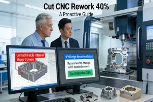
“Un-machinable” features are design elements that significantly increase machining difficulty, cost, and risk of failure. They often hide in plain sight within a 3D model, appearing perfectly logical from a functional standpoint but physically impossible or highly inefficient to produce with a rotating cutting tool. Common culprits include internal sharp corners, which a round tool cannot create; deep, narrow cavities that require fragile, long-reach tools prone to deflection and breakage; and excessively thin walls that chatter and distort during cutting. Identifying and redesigning these features during the design phase is the essence of design for manufacturability (DFM), a proactive step that prevents the need for expensive, time-consuming process engineering and tooling modifications after production has been quoted.
1. The Problem of Deep Pockets, Internal Corners, and Thin Walls
A deep pocket with a high aspect ratio (depth-to-width) forces the use of a long, slender tool. This tool lacks rigidity, leading to vibration (chatter), poor surface finish, dimensional inaccuracy, and a high risk of tool breakage. Similarly, a design demanding a perfectly sharp internal corner is impossible; the smallest radius will be equal to the tool’s radius. Thin walls (e.g., below 1mm for metals) are prone to flexing during machining, causing inaccuracies and even fracture. DFM guidelines recommend minimum wall thicknesses, limiting pocket depth, and using generous fillet radii (at least 1/3 of the cavity depth) to ensure the design is robust enough to survive the machining process itself.
2. Designing for Tool Access and Efficient Machining
Every feature must be accessible to a cutting tool. Undercuts or features on the backside of a part may require a complex, custom fixture or even a second setup, increasing cost and introducing alignment errors. Designs should allow the tool to enter, cut, and exit cleanly. For example, an internal thread that runs to a shoulder without a tool relief groove cannot be machined cleanly. Furthermore, consolidating multiple parts into a single, more complex component can sometimes be more economical than machining and assembling several simple ones, as it reduces part count, assembly time, and potential failure points.
3. Standardizing Features and Optimizing for CNC Kinematics
Complexity begets cost. A part with numerous unique, non-standard hole sizes, thread forms, or corner radii requires constant tool changes, increasing cycle time. DFM encourages standardization: use common drill sizes, standard thread forms, and consistent fillet radii. This allows the machinist to use a smaller set of tools more efficiently. Understanding the step-by-step CNC milling process — how the tool moves and engages with the material — allows designers to create geometries that are not just possible, but optimal for high-speed, accurate machining, directly contributing to the goal of reducing CNC machining errors and costs.
Are Your Tolerances Unnecessarily Tight, Driving Up Cost Without Adding Value?
Applying unnecessarily tight tolerances is a silent but potent cost driver in CNC machining. The relationship between tolerance and cost is exponential; specifying ±0.025mm instead of ±0.1mm on a non-critical feature can double or triple the machining time, necessitate secondary operations like grinding, and require 100% inspection. This “over-engineering” adds no functional value while draining budget and extending lead times. The antidote is a disciplined functional tolerance analysis. This process involves scrutinizing every dimension to determine if it genuinely affects assembly, movement, or performance. Tolerances should be allocated strategically, reserving tight controls only for critical interfaces and applying commercial-grade general tolerances (e.g., per ISO 2768-m) elsewhere.
1. Conducting a Rigorous Functional Analysis
Begin by identifying the datum reference frame and the critical mating features of your part. Which surfaces actually touch or align with other components? Apply tight geometric tolerances (like perpendicularity, true position) only to these interfaces. For example, a bearing journal needs a tight diameter and runout tolerance, but the overall length of the shaft may only need a general tolerance. This “tolerance budgeting” ensures manufacturing effort and cost are concentrated where they are absolutely necessary for function, preventing wasteful expenditure on precision that provides no return.
2. Leveraging Industry Standards for Non-Critical Dimensions
For the vast majority of dimensions that do not affect fit or function, invoke established general tolerance standards. Simply noting “Tolerances per ISO 2768-m” on your drawing communicates to the manufacturer that standard machining practices are acceptable for those features. This eliminates the need to individually tolerance hundreds of non-critical dimensions, simplifies the drawing, and gives the shop the flexibility to use the most efficient, cost-effective processes. It is a professional practice that demonstrates an understanding of practical manufacturing economics and builds trust with your manufacturing partner.
3. The True Cost of “Copy-Paste” or Arbitrary Tolerancing
A common error is copying tolerances from a previous, similar part without critical thought, or applying a blanket “tight” tolerance because it “feels” more precise. Each unnecessarily tight tolerance adds a constraint that the manufacturing process must satisfy, increasing inspection time, scrap risk, and cost. By critically evaluating and strategically loosening non-functional tolerances, engineers can dramatically reduce part cost, shorten lead time, and improve first-pass yield. This disciplined approach is a hallmark of smart engineering innovation and effective project management, ensuring the budget is spent on value, not on unnecessary precision.
How Does the Wrong Surface Finish or Post-Processing Choice Undermine Part Performance?
The selected surface finish and post-processing are not merely cosmetic additions; they are functional extensions of the part’s design. Choosing the wrong finish can lead to catastrophic failure. A medical implant with a conductive coating could cause adverse biological reactions. An outdoor enclosure with insufficient corrosion protection will degrade rapidly. The selection must be driven by the part’s functional requirements: wear resistance, corrosion resistance, electrical conductivity, biocompatibility, cleanability, or specific aesthetic needs. A systematic decision-making process, moving from functional need to a specific finish specification, is essential to ensure the part performs as intended in its end-use environment.
1. Matching Finish to Functional and Environmental Demands
Map the finish directly to the application. For aluminum parts in corrosive environments, anodizing (Type II or III) provides a hard, insulating, and corrosion-resistant layer. For stainless steel requiring maximum corrosion resistance and cleanability (e.g., in food or medical applications), passivation or electropolishing is mandatory. For sliding or wearing surfaces, a hard coating like Titanium Nitride (TiN) or a case-hardening process may be needed. For electrical contacts, bare metal or a conductive plating (e.g., gold, nickel) is required. The finish is an integral part of the component’s performance specification.
2. Understanding Process Interactions and Limitations
Some finishes have inherent constraints. Anodizing adds thickness (typically 0.0005-0.002 inches), which must be accounted for in tight-tolerance dimensions. Plating may not distribute evenly in deep recesses. Furthermore, the sequence of operations is critical. A part needing both a decorative finish and subsequent precision machining should be finished first, then machined on critical features, as machining an anodized surface will ruin the coating. Understanding these interactions prevents costly mistakes where a finish must be stripped and reapplied, or where a part is rendered unusable.
3. Specifying for Compliance and Performance Verification
In regulated industries, the finish is often dictated by standards. Medical devices may require finishes certified to ISO 13485 and FDA guidelines. Aerospace components may need finishes qualified to AMS or MIL specifications. The specification must be precise, including the standard, class, and type. The finish’s performance should also be verifiable. Instead of “smooth finish,” specify a quantitative surface roughness (Ra) value. Instead of “corrosion resistant,” specify a salt spray test duration (e.g., 500 hours per ASTM B117). This precision ensures the finish delivers the required performance and can be objectively verified, turning a potential weakness into a certified strength.
What Does a Truly Collaborative Partnership with a Manufacturer Look Like Beyond RFQ?
A successful manufacturing partnership transcends a simple request-for-quote (RFQ) transaction; it is a deep, technical collaboration built on proactive engineering support, systemic quality assurance, and strategic project alignment. The ideal partner acts as an extension of your engineering team, providing early and actionable design for manufacturability (DFM) feedback to optimize designs before they are finalized. They operate within a certified quality management system (like ISO 9001 or IATF 16949) that ensures process consistency and full traceability. Furthermore, they possess the technical depth and capacity to seamlessly guide a project from prototype validation through to volume production. This collaborative model transforms the supplier from a vendor into a value-creating partner, de-risking the entire production journey. Therefore, when evaluating a manufacturing partner, assess their systemic problem-solving capability. A supplier whose service is built on deep engineering collaboration ensures clients receive parts that are both high-performing and cost-effective.
1. Proactive Engineering Collaboration and DFM Partnership
The first sign of a true partner is proactive engagement. They don’t just quote the print; they analyze it for manufacturability, cost, and performance. They provide detailed, annotated DFM reports suggesting design optimizations — like adjusting a wall thickness, suggesting a more machinable material alternative, or recommending a standard tolerance for a non-critical feature. This collaborative engineering dialogue occurs before the order is placed, de-risking the design and preventing costly changes later. Their goal is to make your part better, faster, and cheaper to produce, aligning their success with yours.
2. Certified Quality Systems and Transparent Processes
A partner’s commitment to quality is evidenced by their certifications and their internal processes. Certifications like ISO 9001:2015 and IATF 16949 are not just plaques on the wall; they represent a framework for consistent process execution, corrective and preventive action (CAPA), and continuous improvement. Look for transparency in their inspection protocols (Do they use CMMs? Provide FAIR reports?) and material traceability. A partner with a robust system provides objective, data-driven proof of quality, giving you confidence that every batch will meet the same high standard as the first article.
3. Strategic Alignment for Prototype-to-Production Scaling
Finally, evaluate the partner’s strategic fit for your project’s lifecycle. Do they have the flexible capacity for rapid prototyping and the scalable systems for production? Is their communication and project management transparent, with a single point of contact and regular updates? The ideal partner’s culture should prioritize long-term collaboration, transparency, and mutual success. They should be invested in helping you navigate not just the first order, but the journey from a handful of prototypes to thousands of production units, ensuring consistency and reliability at every stage. It is precisely the custom CNC milling services provided within the framework of this comprehensive partnership that ultimately ensure the reliable and efficient delivery of precision-milled parts.
Conclusion
Avoiding costly CNC milling errors requires a fundamental shift from a reactive “solve problems” mindset to a proactive “prevent problems” engineering culture. By deeply understanding manufacturing constraints at the design stage, conducting rigorous material and tolerance analysis, and forging a collaborative partnership with a manufacturer possessing systemic engineering capabilities, teams can dramatically increase project predictability, control costs, and accelerate the innovation cycle. This integrated approach transforms manufacturing from a source of risk into a reliable pillar of competitive advantage.
FAQs
Q: What is the fastest way to get a functional metal prototype using CNC milling?
A: Design for machinability using a common material like 6061 aluminum. Provide a clean 3D STEP file and a clear 2D drawing. Partner with a quick-turn prototyping specialist. They can often deliver first articles in 3-5 business days by avoiding complex geometries and non-critical tight tolerances that slow down production.
Q: How can I reduce the cost of CNC milling for my parts?
A: Key strategies include simplifying the design (avoid deep pockets, thin walls), selecting a cost-effective material (e.g., 6061 Al), relaxing non-critical tolerances, and optimizing batch size. The most impactful step is to seek early DFM feedback from your manufacturer, as they can identify cost drivers that are easy to overlook in the design phase.
Q: What’s the difference between 3-axis, 4-axis, and 5-axis CNC milling?
A: 3-axis moves the tool linearly (X, Y, Z), ideal for features on one side. 4-axis adds a rotational axis, allowing machining on multiple sides in one setup. 5-axis adds a second rotational axis, enabling the tool to approach from any angle, which is essential for complex contours, undercuts, and sculpted surfaces and reduces setups for greater accuracy.
Q: How is the quality of CNC milled parts inspected and verified?
A: Quality is verified using precision metrology. First Article Inspection (FAI) with Coordinate Measuring Machines (CMM) checks dimensions against the CAD model. Surface finish is measured with profilometers. Reputable manufacturers provide inspection reports (FAIR) with full traceability, including material certs and process validation data.
Q: What file format should I use when requesting a CNC milling quote?
A: Provide a 3D CAD model in a neutral solid format like STEP (.stp) and a detailed 2D PDF drawing. The drawing must specify all critical dimensions, tolerances, material, and surface finishes. Complete, clear information prevents delays and ensures an accurate quote. Avoid using only STL files for quoting, as they lack precision for manufacturing.
Author Bio
The author is a specialist in precision manufacturing and process optimization, with over 12 years of experience helping hardware teams translate complex designs into high-quality products through technical collaboration. Their expertise is applied within the framework of LS Manufacturing, a precision engineering partner dedicated to providing end-to-end manufacturing solutions from rapid prototyping to volume production. The team operates under a certified management system encompassing ISO 9001, IATF 16949, and AS9100D, ensuring systematic quality and reliability. For a professional DFM analysis and a precise quote on your next project, explore their comprehensive CNC milling capabilities and begin a collaborative partnership.


